Gas turbine and jet propulsion Gas turbine schematic and station numbers Turbine propulsion diagrams dreamer vvti
Gas Turbine Combined Cycle Power Plant System Schematic
Piston engine thrust augmentation Gas turbine combined cycle power plant system schematic Closed cycle gas turbine: construction, working, diagram
Cycle turbine gas combined brayton ramjet thermodynamic nasa power engine plant thermodynamics non grc gov system result shock engineering wave
Brayton cycle engine thrust nasa piston diagram turbine pv pressure volume plot augmentation thermodynamicTurbine gas schematic nasa engine station aircraft numbers number engines parts airplane jet gif modern location each military drawings glenn 8 flow diagram of a simple gas turbine-steam turbine combined powerTurbine diagram gas cycle closed working pv various mechanical booster construction processes used.
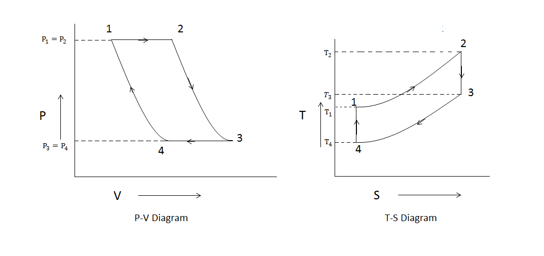
Turbine gas cycle diagram brayton ts pv principle working open closed loopPv and ts diagram of brayton cycle gas turbine .


8 Flow diagram of a simple gas turbine-steam turbine combined power

Gas Turbine Combined Cycle Power Plant System Schematic
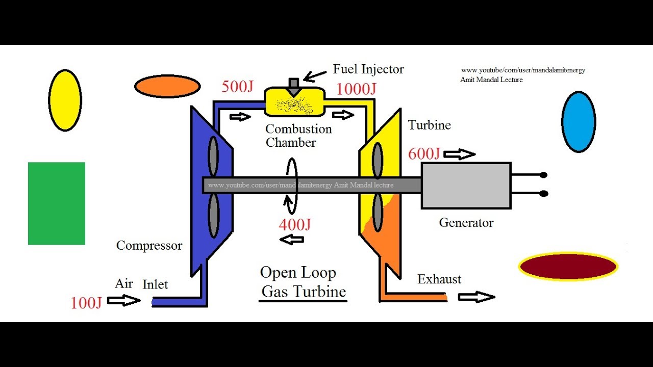
PV and TS diagram of Brayton Cycle Gas Turbine - YouTube

Gas Turbine Schematic and Station Numbers

Gas Turbine and Jet propulsion
Closed Cycle Gas Turbine: Construction, Working, diagram - Mechanical
